How do I fix my digital Speedometer dashboard...and also the Lights for the dashboard

Porn*

Member
Hey there, I just got my first used 89 240sx s13 coupe automatic.

So far I need when i drive the car i see everything works pretty well, but there is few things on the digital dashboard problems like:

I cann't read my speed MPH, if i'm going 30 mph or 45 mph on a road, i try to follow the other cars speed and I try to guess how much speed i'm hitting on school zone, neighborhood or Highway.

Is digital speedometer i would like to know if there is a way to fix that right away... whats the common problems that happens on the speedometer cable or the dashboard, and how to fix that soon as possible.

I forgot to ask 1 more question, when it gets dark at night time, the lights from the dashboard doesn't come out at all, i mean the headlights it works but the dashboard lights it don't work, I feel so dark inside the car driving at night time.

Any Help... thanks
 
Save yourself the hasle and get a analog cluster... Nissan huds break very easily... The HUD in my trackcar is exactly the same... broken!
 
I have never had a problem with mine and I got it from the junkyard lol..


does your speedo not display anything at all?? or is it stuck on KPH?? as for the nothing lighting up part, check your illumination button on the driver side of the steering wheel, there are like 2 arrows one up and one down on a button somewhere, turn the headlights on and then push the up button until it starts lighting up... if that doesnt work, check to see if your tail lights are on when you have the lights turned on, if they dont then you have a blown fuse, its like a 15A somewhere under the dash by the driver side.


if the speedo just doesnt show any numbers at all for speed, then check your speed sensor on the tranny make sure the harness connector is plugged in, its the smallest one underneath there, not too hard to miss. or maybe the digital piece is broken, and in that case go order a new piece or check the junkyards, they are easy to change
 
PORN*!!! Its you!!! Stop following me around all of these clubs! j/k. Hows it going man? am i going to see you friday night at DD?
 
Alchemist XL said:
I have never had a problem with mine and I got it from the junkyard lol..


does your speedo not display anything at all?? or is it stuck on KPH?? as for the nothing lighting up part, check your illumination button on the driver side of the steering wheel, there are like 2 arrows one up and one down on a button somewhere, turn the headlights on and then push the up button until it starts lighting up... if that doesnt work, check to see if your tail lights are on when you have the lights turned on, if they dont then you have a blown fuse, its like a 15A somewhere under the dash by the driver side.


if the speedo just doesnt show any numbers at all for speed, then check your speed sensor on the tranny make sure the harness connector is plugged in, its the smallest one underneath there, not too hard to miss. or maybe the digital piece is broken, and in that case go order a new piece or check the junkyards, they are easy to change


Cool I will try to see what happens and yes my Tail lights are not working at all, both of them..
So I'm going to check the fuse's all of them to see how many fuses is bad, hope it works my speedo once i check and change the fuses, if not i will let you know... thanks for the info.

Blind Drifter said:
PORN*!!! Its you!!! Stop following me around all of these clubs! j/k. Hows it going man? am i going to see you friday night at DD?


Hey Blind Drifter doing good here, i'm trying to fix my 240sx is a coupe it feels very light than the starion, but my coupe 240sx is automatic which is ok for now, may be some day i get to put the sr20det motor with 5 spd, but first i'm working on my starion engine i must finish it first and them i go after the sr20det motor.

Unless i hit the Lotto them i get to finish both cars right away.

I don't know if today/Friday i'm going to be at DD, i just got a call yesterday from work so i might probably work friday, but I will try to see if I go wednsday night HomeDepot parking lot 826 east 57av or is it 47av. i forgot.. but is right there next to the 826East with big sign Home Depot..

Why don't you bring your starion over there, that will be cool. Oh yes are you taking your starion today/Friday or the next Friday.
 
Thas cool Porn*. Im taking my conquest tonight 1/20 to DD. Call em up and ill meet you at Home Depot because i dont know about it but im down for any meets. LATER man
 
I already fix the taillights and is working properly and I check already the fuses underneath the hood, but i'm missing one fuse 20.

Also how can i check my digital speedometer which is not working at all, is hard to drive at night with out the digital speedometer.

On my dashboard everything works, temperature gauge, battery gauge, everything does work but it sucks not having the digital speedometer and also the dashboard lights. It feels pretty dark inside the car driving at night.

Anyone selling a Digital Speedometer in good condition for my 1989 240sx coupe.

I need to get it fix before I get a Speed Ticket...

thanks.
 
Same thing has happened to mine, everything else works perfect except the mph and the HUD, i dunno ima check that plug tommorow. OH! and everythime i press the prake the clock on the speedo turn on as well as the dome light and then when i let go of it it turns off, what can that be?
 
The root of the problem is the connections to the ceramic boards on the HUD unit. The boards are not soldered well and after years of hard suspensions, hot and cold weather time has taken it's toll on these connections. The following pic illustrates where most of the problems lie. The faulty solder joint is on pin #2 from left to right in the picture below. Please note that the HUD is upside-down for this pic. The board that needs re-connecting is the larger of the 2 ceramic boards that are next to each other.

If you are re-soldering this you must have a very fine tip soldering iron and plenty of experience. You may want to hit the other connections on these boards while you are in there just for good measure.
__________________

Most of the problems I have ran into with these is them working under certain hot / cold conditions and then eventually turning off completely. Re-soldering the ceramic boards connectors is always first suspect. There are 3 total ceramic surface mount boards on the HUD units.


hudfix.jpg

__________________


ok, here's one more.

TOPIC: 240SX Digital Speedometer w/HUD.


Can I fix this thing myself? My son has a 1990 240SX that has the digital speedometer w/HUD. The display did not work until the car had been running for 20 to 30 minutes, typical problem with this particular unit I guess. We got enough info to do the repair, from a forum posting that he found, but I want to expound on the steps required, for any other 'do-it-yourselfers' that want to tackle the same problem. I have written with much detail, but most of you will be able to fly right through this procedure and skip alot of reading. If you need the detail, it's here.
This repair focuses on trouble-shooting one specific component on the electronic module, a capacitor. That is the one thing that has failed in other units too.
Please note that this repair requires skill at soldering, a fine pointed soldering tip and a steady hand because the part that you will need to replace is a very small surface-mount capacitor in a rather tight place. IT CAN BE DONE!, we did it.
Also, I suggest that you have someone help you with this task. There are times when a second set of hands make certain things much easier and quicker.

OVERVIEW:
You will be removing the electronic speedometer module and testing a specific capacitor by heating it with a soldering iron. If that part is at fault, you will disassemble the module, remove the faulty part, solder in a new one, retest and hopefully, reassemble the whole rig. This may sound extremely difficult, but it really isn't, there are just alot of steps. It can be accomplished in a couple of hours.

STUFF:
Some things you will need are: #1 & #2 phillips head drivers, needle-nose plier, fine tipped soldering iron, resin-core solder, magnifying lens.
You may want to have onhand, a replacement for the part that we found to be the culprit. Get the smallest 50volt, 1uF, radial lead capacitor that you can find. Below are some possible part numbers:

VendorPhonePart #Electronics Express(800)972-222514ER0501UAllied(800)433-5700852-6604Digi-Key(800)344-4539P5563-ND


PROCEDURE:
* remove the speedometer and gauge cluster
* disassemble the cluster
* test the speedometer module by itself as detailed in the THE TEST: section
* remove and replace the faulty capacitor
* retest module
* reassemble car


----- DETAIL -----

CLUSTER REMOVAL:
There are several plastic moldings that must be removed to get to the gauge cluster. The molding that holds the headlight switches, etc., is the most difficult part. Remove all of the screws that hold it in place. The switches in that molding, to the left of the steering wheel, can remain in the molding. The switches on the right side need to be popped out of the molding. I had to get into a position so that I could see behind the molding and I used a flat bladed driver to push on the lower locking tab of each switch. Push the tab up toward the switch. The bottom of the switch will push out when the tab clears the molding. There is just enough cable to allow you to unplug the switch from the outside of the molding.
Once the switches have been removed from the right side, the steering column must be lowered to make room to remove the molding. There are 2 lower nuts and 2 upper bolts that secure the column. Once the column is loose, lower it only enough to get the molding out, block it to hold it there. Now, the molding around the cluster can be pulled out and swung to the left of the wheel. It can hang there on the wires.
Now remove the 3 screws that hold the cluster in place and pull it out. There are four cables that have to be unpluged. The two larger ones in the center of the cluster have locks on both sides that you squeeze to unlock. The plugs on the left which go directly into the speedometer, only have a lock on the right side. Once the four plugs are out, the cluster can be removed.

CLUSTER DISASSEMBLY:
Detach the ground wire that is protruding through the back, right behind the speedometer module. Also, you will see a small plug toward the bottom side of the module that you need to unplug.
To access the speedometer module, split the cluster assembly by releasing the locking tabs on the back section. Once the cover section of the cluster is off, you will have access to the electronic module. At this point the other gauges will be exposed so be extremely cautious not to touch any of the needles, etc.
Remove the screws that hold the module is place and carefully slide it out. Once out, it is a good idea to snap the cluster back together to protect the other components.

THE TEST:
Heat up your soldering iron.
Hold the module carefully and plug the two cables, from the dash, back into the module. Turn the ignition switch to the RUN position. The speedometer should still be dead (if not, then some other miricle has happened). Touch the tip of the soldering iron on the top of the small capacitor shown in Photo 1 (it looks like a tiny aluminum can). In just a couple of seconds, the speedometer should come to life and dispay a zero. Do not hold the iron on the capacitor for more than a few seconds (ten seconds max), it can make the entire board very hot.

retouch_original.jpg

Photo 1
(This photo is from another person's forum posting.
I have retouched it to define the component in question.)

If the display lights up, remove the iron and let the capacitor cool until the display goes dark, then try again to confirm. If this worked, the capacitor is the problem. Disconnect the cables from the module and go to 'MODULE DISASEMBLY'!
If the unit does not respond, be sure that you are testing the correct component. Reapply heat to the top of the capacitor. If still no response, apply heat to the other capacitors, one at a time. If still no response, then your problem is beyond the scope of this document. Sorry, go back to forum...

MODULE DISASEMBLY:
Work on the module at a well lit bench or table.

To have better access to the faulty capacitor, disasemble the module. First, there is a plug at the end of the top board that must be unplugged. The top board has one screw at the end and two locking standoffs that must be released. Remove the screw. The standoffs can be released one at a time. Carefully squeeze the top of one standoff with needle-nose pliers (don't scratch the board) and just begin to slide the board up. Move to the other standoff and release it. The top board should be free to pull off, it will pull a little hard because there is a connecting header that you are separating as you pull.
Remove the four screws to free the second board. There is a ribbon cable hard-wired to the bottom board so you will only be able to swing the second board to the side for access to the capacitor.

NOTE: The small board that the faulty capacitor is sitting on is at an inconvenient angle to its motherboard. When I bent it out to a more easily accessible angle, one of the connector pins broke loose from the board and I didn't find it until my third attempt at the repair. So be extremely cautious about bending that board, some of those joints are almost impossible to get to for soldering.
 
THE FIX:
You should now have access to the top of the capacitor. I know this sounds strange, but use pliers and pull the top of the capacitor off (the little aluminum can, it pulls off easily). There will be two, fine wires sticking straight up.

NOTE: Pay attention to the polarity of the new capacitor. Although the capacitor will probably work installed either way, the positive lead should be on the left side when looking at the board as in Photo 2.

You may try to solder the capacitor to these wires if you want. If you get a firm solder joint, great! It will work that way. As the forum posting that we read stated, you may want to secure the capacitor from vibration with a spot of hot glue.
I did not have success soldering to these wires. I had to cut the wires close to the base, remove the plastic base and carefully desolder the leads from the board. Be certain that you remove all metal fragments that you desoldered. DO NOT touch any other component with the iron while desoldering and soldering on the board. When you desolder the leads from the pads, there should be only a tiny amount of solder left on the pads.
Before trying to solder the new capacitor onto the board, bend and shape the leads so they are similar to the shape of the one in the photo. Do not attempt to solder the capacitor down and then bend it into position, the pads could pull off the board which would be tragic.
Test the spacing of the leads on the board before trying to solder. Be sure that they fit the pads closely, do not touch each other and do not cross or touch any other component or pad. When you have the leads shaped correctly, tin the leads with a minute amount of solder. Hold the capacitor in place and touch one lead with the iron. Keep the iron in contact with the lead only as long as it takes to melt the solder. When the first lead joint is solid, solder the second lead. Apply more solder if necessary, but not much. These pads are very close to non-connecting traces and a big blob of solder could risk having an electrical short.

newcaplabel.jpg

Photo 2
(This photo shows the new capacitor installed)

Carefully inspect your work with a magnifying lens to insure that the joints are solid and are not overlapping other pads or traces. Also check for and remove any fragments of metal on the board.

newcapclose.jpg

Photo 3
(This closeup photo shows the capacitor leads and pads.
As you can see, there is a big ball of solder on the left pad.
I left it that way since it did not touch any other traces.)

RETEST:
Completely reassemble the electronic module. As with the first test, hold the module carefully and plug the two cables, from the dash, back into the module. Turn the ignition switch to the RUN position. The panel and the HUD should light up and dispay a zero. If so, everything can be reassambled and you are ready for the road. Go to FINALLY.

WHAT THE HECK?!:
If your installation of the new capacitor did not work;
* is the ignition switch in the 'RUN' position?
* are the cable plugs firmly inserted into the back of the module?
* is the plug on the edge of the module reconnected?
* is the header connector between the top board and the second board seated firmly?
* reinspect your solder joints
* look for tiny pieces of metal (from cutting or desoldering) laying on the board or against other components
* did any of the copper traces on the board get deeply scratched (broken)?
* check the solder joints of the pins that connect the 'capacitor board' to its mother board (Photo 2)
* try another new capacitor
Go to RETEST.


FINALLY:

YeHaa!

We hope that you had as much fun (hmmm...?) as we did, replacing this tiny part. We just considered it another challenge in the long list of challenges associated with automobiles!

'While driving, take no risks, be no threat'
__________________


and annother one, damn... i must be bored?


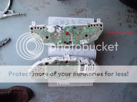
I searched in many groups about my cluster problem to no avail. I just installed an HUD cluster on my 1989 S13 SOHC.

Symptoms: a week later after cluster installation, I try to shut my car off and all my ACC items will stay on, radio,heater, cluster lights,etc. I thought it was a ignition switch problem. I try restarting the car and it went away...but later that day I noticed that the driving lights and cluster lights were still on, even with the lights switch off and the flip ups were staying up permamently...Something was shorting my illumination path to ground. I went directly to the cluster and double check the harness just in case. I found that by disconnecting the cluster the problem went away...I never trouble shoot a cluster of any kind before, and would like to share my findings.
Troubleshooting: Is not too much to it, and it applies to analog/HUD and maybe even DOHC cluster. Measure all the diodes in the back of cluster. If you find any that are shorten out, replace them. I used old ones from an analog cluster I have for parts. The diodes are the same. Check the pics for the location of the diodes. They handle the illumination of the cluster and clock. Also tied up with the car light system. If you can find an FSM, look up the wire diagram, these two diodes are tied up on one side and by shorting out they were grounding the lights on the car, also confusing the time control unit and creating other issues...flip ups staying up and the ACC function staying on.. After replacing the diodes, all problems solved. Ensure if you have an HUD that your connector for the HUD LCD module is on, if not you will not have cluster illumination. Also to have the blinkers switch connected if not you will not have turn signals, just to keep you from getting confused during final testing. Sorry about the long post, hopefully somebody outhere will benefit from this. And now the pics......
sidebyside.jpg

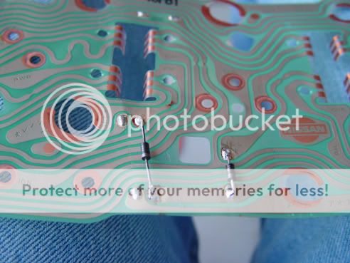
Here you can see the location of the specific diodes and the cannibalized analog cluster, plus a top view of my shoe....
tongue.gif


generalview.jpg

A good look of the flex mat circuit board, BE CAREFUL when handling this part is very delicate....also ensure that you maintain the polarity of the diodes, they only go one way and one way only.
closeup.jpg

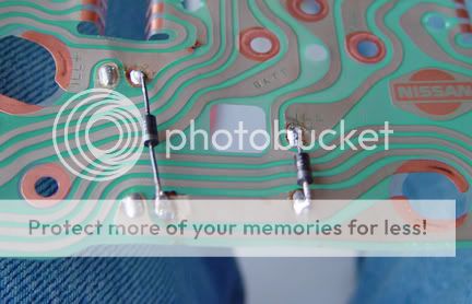
An even closer look, not a perfect soldering job, but it will do....Also you might notice that I soldered the diodes in the wrong side of the board, I had to because I used the old diodes and cut them off from the other cluster and they were too short to be soldered on the back of the HUD cluster. But actually is better this way, because if you need to replace them in the future you will not have to take the circuit board and all lightbulbs to have access to it...just make sure they dont touch any metal in the dash when installed....
essentialtools.jpg

Just to give an idea what tools you are going to need......do not apply too much heat to the components or you will damage the tracks on the flex circuit board.....
badboy.gif


When you measure diodes, with a multimeter you are looking for a high (ohm) (open circuit)resistance reading with the meter leads measuring across the diode. You will not need power on the cluster to measure resistance (ohms). Now inverse the location of the leads and you get a low (close circuit) resistance reading or almost 0 ohms.....With the bad diodes on my cluster I was getting 0 ohms both ways which indicates a short condition which is not the way diodes work...therefore acting as an piece of wire and grounding the circuit and creating all kinds of fun...
badboy.gif

If you like, find a diode somewhere and check it....just for practice and to get an idea of what to look for....they work based on polarity (+) and (-) so by reversing the leads you are simulating the two basic operational conditions of a diode......If you look at the diode theres a little silver band or mark (indicates negative side) on them...thats what you use to orient the diode, so remember which way the original one was facing and make sure the new matches the same orientation.....
When you take the circuit board off the cluster you will see the resistor and 3 or 4 diodes (depending of what type cluster), they are in the back of the flexible circuit board...I replaced the diodes on the original locations of the bad ones but on the opposite side, so instead of being on the inside now they are on the outside...better cool down
naughty.gif

Im trying to track the diodes by the markings, should be no problem matching these with a commercial replacement...when I find the right replacement I will update the thread. I see your point, without an extra cluster or parts there will is no way you can repair it...I think a lot of people have lights problem and go crazy thinking something is shorten out, bad switch or miswire when is actually the cluster on the car
redface.gif
rolleyes2.gif

After inspecting all the diodes on the cluster, I noticed that they tend to get pretty hot, which might be the main reason why the fail after a while...so make sure when you replace them that you leave enough spacing between diode and circuit board ( bend the diode legs before soldering to where the diode sits high on the circuit) so the heat does not damage the circuits..... hope this helps
 
Back
Top Bottom