I did not write all of this. The only credit I deserve is taking the time to copy everything over for you all.
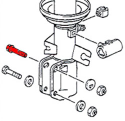
S13 Bushing Diagram

2- TC(tension rod)
4- LCA(lower control arm) front
6- LCA rear
8- Forward link (traction rod)
10- Rear Upper arm
12- Toe link
14- Upright (upper)
15- Upright (lower)
16- Sub-frame (front/lower)
17- Sub-frame (rear/upper)
Springs
Spring rate and ride height information
STOCK
Spring Rate - F : 2.0kg/mm (2.2 for sport package?)
Spring Rate - R : 2.0kg/mm (2.2 for sport package?)
Ride Height - F : 0"
Ride Height - R : 0"
EIBACH PROKIT
Spring Rate - F : 1.84~1.92kg/mm
Spring Rate - R : 2.3~2.4kg/mm
Ride Height - F : -1.8" (eibach site) -1" (jnm240 test)
Ride Height - R : -1.6" (eibach site) -.75" (test)
EIBACH SPORTLINE
Spring Rate - F : 1.92~2.0kg/mm
Spring Rate - R : 2.4~2.5kg/mm
Ride Height - F : -2.2" / -1.75" (test)
Ride Height - R : -2.1" / -1.75" (test)
H & R SPORT
Spring Rate - F : 2.0~2.08kg/mm
Spring Rate - R : 2.5~2.6kg/mm
Ride Height - F : -1.3"
Ride Height - R : -1.3"
TEIN S-TECH
(progressive, TEIN only lists the maximal rate)
Spring Rate - F : 3.7
Spring Rate - R : 3.2
Ride Height - F : -1.5"
Ride Height - R : -1.2"
TEIN HIGH-TECH
Spring Rate - F: 3.3 (s13); 3.2 (s14)
Spring Rate - R: 2.9 (s13); 3.1 (s14)
Ride Height - F: -0.9" (s13); -0.7" (s14)
Ride Height - R: -0.6" (s13); -0.4" (s14)
INTRAX SPORT SPRING KIT
Spring Rate - F : (Couldn't get through to tech support)
Spring Rate - R : (Couldn't get through to tech support)
Ride Height - F : -2.25"
Ride Height - R : -2.0"
SUSPENSION TECHNIQUES
Spring Rate - F : 3
Spring Rate - R : 2.66
Ride Height - F : -1.3"
Ride Height - R : -1.3" (?)
WHITELINE CONTROL
Spring Rate - F : S13&S14 = 2.8
Spring Rate - R : S13= 2.36~3.66 S14= 1.91~3.18
Ride Height - F : -1.75"
Ride Height - R : -1.75"
TANABE GF210
Spring Rate - F : 2.9
Spring Rate - R : 2.7
Ride Height - F : -1." to -1.6"
Ride Height - R : -.6" to -1"
RS*R DOWN SPRINGS
Spring Rate - F: 3.0
SPring Rate - R: 3.0
Ride Height - F: -1.6"(s13) -1.0"(s14)
Ride Height - R: -1.2" (s13) -0.6" (s14)
RS*R RACE SPRINGS
Spring Rate - F: 5.0
Spring Rate - R: 4.5(s13) 4.2 (s14)
Ride Height - F: -1.4"
Ride Height - R: -1.2" (s13) -1.0" (s14)
MEGAN RACING LOWERING SPRINGS MR-LS-NS13 (s13):
Springrate F: 6.25kg/mm (350lbs/in)
Springrate R: 4.46kg/mm (250lbs/in)
Ride Height F: 1.75"
Ride Height R: 1.75"
MEGAN RACING LOWERING SPRINGS MR-LS-NS14 (s14):
Springrate F: 6.25kg/mm (350lbs/in)
Springrate R: 4.46kg/mm (250lbs/in)
Ride Height F: 1.75"
Ride Height R: 1.75"
ESPELIR ACTIVE SUPER DOWN -
Front - 3.0kg/mm (168.0 lb/in) ~ drops 1.9"
Rear - 2.4kg/mm (134.4 lb/in) ~ drops 1.1"
KGMM S21 SPORT -
Front - 3.2kg/mm (179.2 lb/in)
Rear - 2.6kg/mm (145 lb/in)
KGMM S21 SUPERSPORT -
Front - 4.6kg/mm (257.6 lb/in)
Rear - 3.8kg/mm (212.8 lb/in)
KGMM DR Race -
Front - 6kg/mm
Rear - 5kg/mm
Ride Height - F: 2.2"
Ride Height - R: 1.2"
5ZIGEN R-RATE -
Front - 2.4 to 5.2kg/mm (134 to 291 lb/in) ~ drops 1.3"
Rear - 1.9 to 5.0kg/mm (106 to 280 lb/in) ~ drops 1.1"
KGMM S21 RACE -
Front - 6.6kg/mm (369.6 lb/in) ~drops ?"
Rear - 5.2kg/mm (291.2 lb/in) ~ drops ?"
Coilovers
Buddy Club Racing Spec Damper
15 way adjustable, ride height adjustable
Spring Rate - front(8kg/mm)
Spring Rate - rear(6kg/mm)
Height adj. - F(?) inch
Height adj. - R(?) inch
Cusco Comp-S
ride height adjustable
Spring Rate - front(7kg/mm)
Spring Rate - rear(5kg/mm)
Height adj. - F(-75 ~ -50) mm
Height adj. - R(-50 ~ -20) mm
Cusco Zero 1
ride height adjustable
Spring Rate - front(7kg/mm)
Spring Rate - rear(5kg/mm)
Height adj. - F(-90 ~ 0) mm
Height adj. - R(-65 ~ 0) mm
Cusco Zero2
5 way adjustable, ride height adjustable
Spring Rate - front(7kg/mm)
Spring Rate - rear(5kg/mm)
Height adj. - F(-90 ~ 0) mm
Height adj. - R(-65 ~ 0) mm
Cusco Zero2R
5 way adjustable, ride height adjustable
Spring Rate - front(7kg/mm)
Spring Rate - rear(5kg/mm)
Height adj. - F(-85 ~ 0) mm
Height adj. - R(-70 ~ 0) mm
GP Sports G-Master
32 way adjustable, ride height adjustable
Spring Rate - front(8kg/mm)
Spring Rate - rear(6kg/mm)
Height adj. - F(?) inch
Height adj. - R(?) inch
HKS Hipermax DRAG
30 way adjustable, ride height adjustable
Spring Rate - front(4kg/mm)
Spring Rate - rear(3kg/mm)
Height adj. - F(?) inch
Height adj. - R(?) inch
HKS Hipermax II
30 way adjustable, ride height adjustable
Spring Rate - front(7kg/mm)
Spring Rate - rear(5kg/mm)
Height adj. - F(?) inch
Height adj. - R(?) inch
JIC FLT-A1
5 way adjustable, ride height adjustable
Spring Rate - front(7kg/mm)
Spring Rate - rear(5kg/mm)
Height adj. - F(0.5 ~ 0.25) inch
Height adj. - R(0.5 ~ 0.25) inch
JIC FLT-A2
15 way adjustable, ride height adjustable
Spring Rate - front(7kg/mm)
Spring Rate - rear(5kg/mm)
Height adj. - F(0.5 ~ 0.25) inch
Height adj. - R(0.5 ~ 0.25) inch
Ksport Kontrol Pro
36 way adjustable, ride height adjustable
Spring Rate - front(7kg/mm)
Spring Rate - rear(5kg/mm)
Height adj. - F(?) inch
Height adj. - R(?) inch
KTS Coilovers
15 way adjustable, ride height adjustable
Spring Rate - front(8kg/mm)
Spring Rate - rear(6kg/mm)
Height adj. - F(?) inch
Height adj. - R(?) inch
Megan Racing Coilover Kit
32 way adjustable, ride height adjustable
Spring Rate - front(8kg/mm)
Spring Rate - rear(6kg/mm)
Height adj. - F(?) inch
Height adj. - R(?) inch
Silk Road RM/A8
8 way adjustable, ride height adjustable
Spring Rate - front(8kg/mm) or (8kg/mm)
Spring Rate - rear(6kg/mm) or (7kg/mm)
Height adj. - F(?) inch
Height adj. - R(?) inch
Stance
15 way adjustable, ride height adjustable
Spring Rate - front(8kg/mm) or (9kg/mm)
Spring Rate - rear(6kg/mm) or (7kg/mm)
Height adj. - F() inch
Height adj. - R() inch
Tanabe Sustec Pro DD
4 way adjustable, ride height adjustable
Spring Rate - front(8kg/mm)
Spring Rate - rear(6kg/mm)
Height adj. - F(-0.5 ~ -2.5) inch
Height adj. - R(-0.5 ~ -2.5) inch
Tanabe Sustec Pro SS
4 way front and 4 or 8 way rear adjustable, ride height adjustable
Spring Rate - front(8kg/mm)
Spring Rate - rear(6kg/mm)
Height adj. - F(-0.5 ~ -2.5) inch
Height adj. - R(-0.5 ~ -2.5) inch
Tanabe Sustec Pro SS Type II
4 way front and 4 or 8 way rear adjustable, ride height adjustable
Spring Rate - front(8kg/mm)
Spring Rate - rear(6kg/mm)
Height adj. - F(-0.5 ~ -2.5) inch
Height adj. - R(-0.5 ~ -2.5) inch
Tanabe Sustec S-OC
? way adjustable, ride height adjustable
Spring Rate - front(8kg/mm)
Spring Rate - rear(6kg/mm)
Height adj. - F(-0.5 ~ -2.5) inch
Height adj. - R(-0.5 ~ -2.5) inch
Tanabe Sustec S-OC Type II
? way adjustable, ride height adjustable
Spring Rate - front(8kg/mm)
Spring Rate - rear(6kg/mm)
Height adj. - F(-0.5 ~ -2.5) inch
Height adj. - R(-0.5 ~ -2.5) inch
Tein Basic Damper
ride height adjustable
Spring Rate - front(6kg/mm)
Spring Rate - rear(5kg/mm)
Height adj. - F(-1.0 ~ -2.5) inch
Height adj. - R(-1.1 ~ -2.9) inch
Tein Super Street
16 way adjustable (compression and rebound combined), ride height adjustable
Spring Rate - front(6kg/mm)
Spring Rate - rear(5kg/mm)
Height adj. - F(-0.7 ~ -2.2) inch
Height adj. - R(-0.1 ~ -2.5) inch
Tein Super Drift
16 way adjustable (compression and rebound combined), ride height adjustable
Spring Rate - front(10kg/mm)
Spring Rate - rear(8kg/mm)
Height adj. - F(-0.2 ~ -3.2) inch
Height adj. - R(-0.3 ~ -2.6) inch
Tein Type FLEX
16 way adjustable (compression and rebound combined), ride height adjustable
Spring Rate - front(5kg/mm)
Spring Rate - rear(4kg/mm)
Height adj. - F(-0.1 ~ -2.5) inch
Height adj. - R(-0.8 ~ -2.4) inch
Zeal Function B6
6 way adjustable, ride height adjustable
Spring Rate - front(6kg/mm)
Spring Rate - rear(5kg/mm)
Height adj. - F(?) inch
Height adj. - R(?) inch
Differentials -
There are various types of LSDs. For our cars, there are Viscous, which uses a fluid filled sac that expands with heat (Fritction) to lock the output shafts, and then there are mechanical. Mechanical means that the LSD in engaged or not due to interaction between 2 (or more) set, mechanical parts. This category includes CLUTCH and HELICAL type LSDs.
For road racing, Helical type is more desirable, because it acts like an open diff while turning in and such. If I am not mistaken, it does not lock the two output shafts to spin at the same rate, but rather it biases torque to the wheel with more grip up to 80%.
Ok, other type of Mechanical LSD, clutch type. Clutch type LSDs use a center cam that moves under torque changes within a casing. The casing is 2 parts (L and R) and is symetrical in that sense. However, the cuts in the casing making the notches for the cam to slide in are not. That determines 1, 1.5, or 2 way LSD. As the cam slids in the notch it pushes the casing outward, which engages a series of clutch discs, some attached to the casing, some to the output shafts. When engaged, both output shafts will rotate at the speed of the casing, making both axles, and subsequently, wheels, rotate at the same speed.
Now back to the notches:
A 1 way notch is cut like an upside down triangle. While the cam can push backward against the tapered edges, expanding the casing, it cannot push forward against the flat surface. Therefore under acceleration torque (cam rotating backwards) it will lock, and under deceleration torque, when the cam is forced to rotate forward due to forces from braking, engine braking, etc.. it will just contact a flat "wall" and the casing will not expand.
A 1.5 way notch is like an upside down triangle with a half trangle on top of it. During acceleration it will expand the casing at one rate, and during deceleration, it will still expand the casing, but due to the cuts' higher angles, it will require more force to move the casing apart. Therefore, only during Very hard braking will it have enough force pushing it forward to expand the casing.
Need it be said that a 2 way then is shaped just about like a diamond? Where it requires almost the same amount of acceleration or deceleration to force the casing apart. Usually, the top cuts are slightly more dramatic, making the 2 way still require slighlty more deceleration force to push the cam to expand the casing.
Ok, there is more. The more the casing expands, the more clutches contact each other, and the more the output shafts get locked into the same rotation. Now there are adjustable diffs where you can set a breakaway torque. That means that the cluch discs get moved closer together or further apart to dictate the SOFT, MED, or HARD setting. The closer the clutch plates are to each other, the sooner the output shafts, and thus the wheels, will spin in sync.
Sway bar information
S13
Stock ? (data from Japanparts.com) JDM ?
Front 24mm
Rear 16mm
Suspension Techniques (data from STRacing.com)
Front 27mm
Rear 20.6mm
Whiteline (data from PDMRacing.com)
Front 27mm
Rear 20-22mm
Cusco (data from Japanparts.com)
Front 28mm
Rear 18mm
Tanabe (data from Tanabe-usa.com)
Front 30.4mm
Rear 22mm
Progress
Front 27mm
Rear 22mm
S14
Stock (data from CourtesyParts)
Front 27.2mm
Rear 15.9mm
Whiteline Adjustables (data from PDMRacing.com)
Front 27mm
Rear 20mm (22mm available as well)
Suspension Techniques (data from STRacing.com)
Front 28.6mm
Rear 20.6mm
Cusco (data from Japanparts.com)
Front 30mm
Rear 21mm
Nismo (data from Japanparts.com)
Front 30mm
Rear 23mm
Tanabe (data from Tanabe-usa.com)
Front 30.4mm
Rear 27.5mm
Progress
Front 30mm
Rear 24mm
Spring/shock adjustment guide
Spring Rate Changes (def. important for those who dont pay att. to this)
Modification - Effect on Suspension
Increase front and rear rate - Ride harshness increases; tires may not follow bumps causing reduced traction. Roll resistance increases.
Increase front rate only - Front ride rate increases. Front roll resistance increases, increasing understeer or reducing oversteer.
Increase rear rate only - Rear ride rate increases. Rear roll resistance increases, increasing oversteer or reducing understeer.
Decrease front and rear rate - Ride harshness decreases; tires follow bumps more effectively, possibly improving traction. Roll resistance decreases.
Decrease front rate only - Front ride rate decreases. Front roll resistance decreases, decreasing understeer or increasing oversteer.
Decrease rear rate only - Rear ride rate decreases. Rear roll resistance decreases, decreasing oversteer or increasing understeer.
S13 Bushing Diagram
2- TC(tension rod)
4- LCA(lower control arm) front
6- LCA rear
8- Forward link (traction rod)
10- Rear Upper arm
12- Toe link
14- Upright (upper)
15- Upright (lower)
16- Sub-frame (front/lower)
17- Sub-frame (rear/upper)
Springs
Spring rate and ride height information
STOCK
Spring Rate - F : 2.0kg/mm (2.2 for sport package?)
Spring Rate - R : 2.0kg/mm (2.2 for sport package?)
Ride Height - F : 0"
Ride Height - R : 0"
EIBACH PROKIT
Spring Rate - F : 1.84~1.92kg/mm
Spring Rate - R : 2.3~2.4kg/mm
Ride Height - F : -1.8" (eibach site) -1" (jnm240 test)
Ride Height - R : -1.6" (eibach site) -.75" (test)
EIBACH SPORTLINE
Spring Rate - F : 1.92~2.0kg/mm
Spring Rate - R : 2.4~2.5kg/mm
Ride Height - F : -2.2" / -1.75" (test)
Ride Height - R : -2.1" / -1.75" (test)
H & R SPORT
Spring Rate - F : 2.0~2.08kg/mm
Spring Rate - R : 2.5~2.6kg/mm
Ride Height - F : -1.3"
Ride Height - R : -1.3"
TEIN S-TECH
(progressive, TEIN only lists the maximal rate)
Spring Rate - F : 3.7
Spring Rate - R : 3.2
Ride Height - F : -1.5"
Ride Height - R : -1.2"
TEIN HIGH-TECH
Spring Rate - F: 3.3 (s13); 3.2 (s14)
Spring Rate - R: 2.9 (s13); 3.1 (s14)
Ride Height - F: -0.9" (s13); -0.7" (s14)
Ride Height - R: -0.6" (s13); -0.4" (s14)
INTRAX SPORT SPRING KIT
Spring Rate - F : (Couldn't get through to tech support)
Spring Rate - R : (Couldn't get through to tech support)
Ride Height - F : -2.25"
Ride Height - R : -2.0"
SUSPENSION TECHNIQUES
Spring Rate - F : 3
Spring Rate - R : 2.66
Ride Height - F : -1.3"
Ride Height - R : -1.3" (?)
WHITELINE CONTROL
Spring Rate - F : S13&S14 = 2.8
Spring Rate - R : S13= 2.36~3.66 S14= 1.91~3.18
Ride Height - F : -1.75"
Ride Height - R : -1.75"
TANABE GF210
Spring Rate - F : 2.9
Spring Rate - R : 2.7
Ride Height - F : -1." to -1.6"
Ride Height - R : -.6" to -1"
RS*R DOWN SPRINGS
Spring Rate - F: 3.0
SPring Rate - R: 3.0
Ride Height - F: -1.6"(s13) -1.0"(s14)
Ride Height - R: -1.2" (s13) -0.6" (s14)
RS*R RACE SPRINGS
Spring Rate - F: 5.0
Spring Rate - R: 4.5(s13) 4.2 (s14)
Ride Height - F: -1.4"
Ride Height - R: -1.2" (s13) -1.0" (s14)
MEGAN RACING LOWERING SPRINGS MR-LS-NS13 (s13):
Springrate F: 6.25kg/mm (350lbs/in)
Springrate R: 4.46kg/mm (250lbs/in)
Ride Height F: 1.75"
Ride Height R: 1.75"
MEGAN RACING LOWERING SPRINGS MR-LS-NS14 (s14):
Springrate F: 6.25kg/mm (350lbs/in)
Springrate R: 4.46kg/mm (250lbs/in)
Ride Height F: 1.75"
Ride Height R: 1.75"
ESPELIR ACTIVE SUPER DOWN -
Front - 3.0kg/mm (168.0 lb/in) ~ drops 1.9"
Rear - 2.4kg/mm (134.4 lb/in) ~ drops 1.1"
KGMM S21 SPORT -
Front - 3.2kg/mm (179.2 lb/in)
Rear - 2.6kg/mm (145 lb/in)
KGMM S21 SUPERSPORT -
Front - 4.6kg/mm (257.6 lb/in)
Rear - 3.8kg/mm (212.8 lb/in)
KGMM DR Race -
Front - 6kg/mm
Rear - 5kg/mm
Ride Height - F: 2.2"
Ride Height - R: 1.2"
5ZIGEN R-RATE -
Front - 2.4 to 5.2kg/mm (134 to 291 lb/in) ~ drops 1.3"
Rear - 1.9 to 5.0kg/mm (106 to 280 lb/in) ~ drops 1.1"
KGMM S21 RACE -
Front - 6.6kg/mm (369.6 lb/in) ~drops ?"
Rear - 5.2kg/mm (291.2 lb/in) ~ drops ?"
Coilovers
Buddy Club Racing Spec Damper
15 way adjustable, ride height adjustable
Spring Rate - front(8kg/mm)
Spring Rate - rear(6kg/mm)
Height adj. - F(?) inch
Height adj. - R(?) inch
Cusco Comp-S
ride height adjustable
Spring Rate - front(7kg/mm)
Spring Rate - rear(5kg/mm)
Height adj. - F(-75 ~ -50) mm
Height adj. - R(-50 ~ -20) mm
Cusco Zero 1
ride height adjustable
Spring Rate - front(7kg/mm)
Spring Rate - rear(5kg/mm)
Height adj. - F(-90 ~ 0) mm
Height adj. - R(-65 ~ 0) mm
Cusco Zero2
5 way adjustable, ride height adjustable
Spring Rate - front(7kg/mm)
Spring Rate - rear(5kg/mm)
Height adj. - F(-90 ~ 0) mm
Height adj. - R(-65 ~ 0) mm
Cusco Zero2R
5 way adjustable, ride height adjustable
Spring Rate - front(7kg/mm)
Spring Rate - rear(5kg/mm)
Height adj. - F(-85 ~ 0) mm
Height adj. - R(-70 ~ 0) mm
GP Sports G-Master
32 way adjustable, ride height adjustable
Spring Rate - front(8kg/mm)
Spring Rate - rear(6kg/mm)
Height adj. - F(?) inch
Height adj. - R(?) inch
HKS Hipermax DRAG
30 way adjustable, ride height adjustable
Spring Rate - front(4kg/mm)
Spring Rate - rear(3kg/mm)
Height adj. - F(?) inch
Height adj. - R(?) inch
HKS Hipermax II
30 way adjustable, ride height adjustable
Spring Rate - front(7kg/mm)
Spring Rate - rear(5kg/mm)
Height adj. - F(?) inch
Height adj. - R(?) inch
JIC FLT-A1
5 way adjustable, ride height adjustable
Spring Rate - front(7kg/mm)
Spring Rate - rear(5kg/mm)
Height adj. - F(0.5 ~ 0.25) inch
Height adj. - R(0.5 ~ 0.25) inch
JIC FLT-A2
15 way adjustable, ride height adjustable
Spring Rate - front(7kg/mm)
Spring Rate - rear(5kg/mm)
Height adj. - F(0.5 ~ 0.25) inch
Height adj. - R(0.5 ~ 0.25) inch
Ksport Kontrol Pro
36 way adjustable, ride height adjustable
Spring Rate - front(7kg/mm)
Spring Rate - rear(5kg/mm)
Height adj. - F(?) inch
Height adj. - R(?) inch
KTS Coilovers
15 way adjustable, ride height adjustable
Spring Rate - front(8kg/mm)
Spring Rate - rear(6kg/mm)
Height adj. - F(?) inch
Height adj. - R(?) inch
Megan Racing Coilover Kit
32 way adjustable, ride height adjustable
Spring Rate - front(8kg/mm)
Spring Rate - rear(6kg/mm)
Height adj. - F(?) inch
Height adj. - R(?) inch
Silk Road RM/A8
8 way adjustable, ride height adjustable
Spring Rate - front(8kg/mm) or (8kg/mm)
Spring Rate - rear(6kg/mm) or (7kg/mm)
Height adj. - F(?) inch
Height adj. - R(?) inch
Stance
15 way adjustable, ride height adjustable
Spring Rate - front(8kg/mm) or (9kg/mm)
Spring Rate - rear(6kg/mm) or (7kg/mm)
Height adj. - F() inch
Height adj. - R() inch
Tanabe Sustec Pro DD
4 way adjustable, ride height adjustable
Spring Rate - front(8kg/mm)
Spring Rate - rear(6kg/mm)
Height adj. - F(-0.5 ~ -2.5) inch
Height adj. - R(-0.5 ~ -2.5) inch
Tanabe Sustec Pro SS
4 way front and 4 or 8 way rear adjustable, ride height adjustable
Spring Rate - front(8kg/mm)
Spring Rate - rear(6kg/mm)
Height adj. - F(-0.5 ~ -2.5) inch
Height adj. - R(-0.5 ~ -2.5) inch
Tanabe Sustec Pro SS Type II
4 way front and 4 or 8 way rear adjustable, ride height adjustable
Spring Rate - front(8kg/mm)
Spring Rate - rear(6kg/mm)
Height adj. - F(-0.5 ~ -2.5) inch
Height adj. - R(-0.5 ~ -2.5) inch
Tanabe Sustec S-OC
? way adjustable, ride height adjustable
Spring Rate - front(8kg/mm)
Spring Rate - rear(6kg/mm)
Height adj. - F(-0.5 ~ -2.5) inch
Height adj. - R(-0.5 ~ -2.5) inch
Tanabe Sustec S-OC Type II
? way adjustable, ride height adjustable
Spring Rate - front(8kg/mm)
Spring Rate - rear(6kg/mm)
Height adj. - F(-0.5 ~ -2.5) inch
Height adj. - R(-0.5 ~ -2.5) inch
Tein Basic Damper
ride height adjustable
Spring Rate - front(6kg/mm)
Spring Rate - rear(5kg/mm)
Height adj. - F(-1.0 ~ -2.5) inch
Height adj. - R(-1.1 ~ -2.9) inch
Tein Super Street
16 way adjustable (compression and rebound combined), ride height adjustable
Spring Rate - front(6kg/mm)
Spring Rate - rear(5kg/mm)
Height adj. - F(-0.7 ~ -2.2) inch
Height adj. - R(-0.1 ~ -2.5) inch
Tein Super Drift
16 way adjustable (compression and rebound combined), ride height adjustable
Spring Rate - front(10kg/mm)
Spring Rate - rear(8kg/mm)
Height adj. - F(-0.2 ~ -3.2) inch
Height adj. - R(-0.3 ~ -2.6) inch
Tein Type FLEX
16 way adjustable (compression and rebound combined), ride height adjustable
Spring Rate - front(5kg/mm)
Spring Rate - rear(4kg/mm)
Height adj. - F(-0.1 ~ -2.5) inch
Height adj. - R(-0.8 ~ -2.4) inch
Zeal Function B6
6 way adjustable, ride height adjustable
Spring Rate - front(6kg/mm)
Spring Rate - rear(5kg/mm)
Height adj. - F(?) inch
Height adj. - R(?) inch
Differentials -
There are various types of LSDs. For our cars, there are Viscous, which uses a fluid filled sac that expands with heat (Fritction) to lock the output shafts, and then there are mechanical. Mechanical means that the LSD in engaged or not due to interaction between 2 (or more) set, mechanical parts. This category includes CLUTCH and HELICAL type LSDs.
For road racing, Helical type is more desirable, because it acts like an open diff while turning in and such. If I am not mistaken, it does not lock the two output shafts to spin at the same rate, but rather it biases torque to the wheel with more grip up to 80%.
Ok, other type of Mechanical LSD, clutch type. Clutch type LSDs use a center cam that moves under torque changes within a casing. The casing is 2 parts (L and R) and is symetrical in that sense. However, the cuts in the casing making the notches for the cam to slide in are not. That determines 1, 1.5, or 2 way LSD. As the cam slids in the notch it pushes the casing outward, which engages a series of clutch discs, some attached to the casing, some to the output shafts. When engaged, both output shafts will rotate at the speed of the casing, making both axles, and subsequently, wheels, rotate at the same speed.
Now back to the notches:
A 1 way notch is cut like an upside down triangle. While the cam can push backward against the tapered edges, expanding the casing, it cannot push forward against the flat surface. Therefore under acceleration torque (cam rotating backwards) it will lock, and under deceleration torque, when the cam is forced to rotate forward due to forces from braking, engine braking, etc.. it will just contact a flat "wall" and the casing will not expand.
A 1.5 way notch is like an upside down triangle with a half trangle on top of it. During acceleration it will expand the casing at one rate, and during deceleration, it will still expand the casing, but due to the cuts' higher angles, it will require more force to move the casing apart. Therefore, only during Very hard braking will it have enough force pushing it forward to expand the casing.
Need it be said that a 2 way then is shaped just about like a diamond? Where it requires almost the same amount of acceleration or deceleration to force the casing apart. Usually, the top cuts are slightly more dramatic, making the 2 way still require slighlty more deceleration force to push the cam to expand the casing.
Ok, there is more. The more the casing expands, the more clutches contact each other, and the more the output shafts get locked into the same rotation. Now there are adjustable diffs where you can set a breakaway torque. That means that the cluch discs get moved closer together or further apart to dictate the SOFT, MED, or HARD setting. The closer the clutch plates are to each other, the sooner the output shafts, and thus the wheels, will spin in sync.
Sway bar information
S13
Stock ? (data from Japanparts.com) JDM ?
Front 24mm
Rear 16mm
Suspension Techniques (data from STRacing.com)
Front 27mm
Rear 20.6mm
Whiteline (data from PDMRacing.com)
Front 27mm
Rear 20-22mm
Cusco (data from Japanparts.com)
Front 28mm
Rear 18mm
Tanabe (data from Tanabe-usa.com)
Front 30.4mm
Rear 22mm
Progress
Front 27mm
Rear 22mm
S14
Stock (data from CourtesyParts)
Front 27.2mm
Rear 15.9mm
Whiteline Adjustables (data from PDMRacing.com)
Front 27mm
Rear 20mm (22mm available as well)
Suspension Techniques (data from STRacing.com)
Front 28.6mm
Rear 20.6mm
Cusco (data from Japanparts.com)
Front 30mm
Rear 21mm
Nismo (data from Japanparts.com)
Front 30mm
Rear 23mm
Tanabe (data from Tanabe-usa.com)
Front 30.4mm
Rear 27.5mm
Progress
Front 30mm
Rear 24mm
Spring/shock adjustment guide
Spring Rate Changes (def. important for those who dont pay att. to this)
Modification - Effect on Suspension
Increase front and rear rate - Ride harshness increases; tires may not follow bumps causing reduced traction. Roll resistance increases.
Increase front rate only - Front ride rate increases. Front roll resistance increases, increasing understeer or reducing oversteer.
Increase rear rate only - Rear ride rate increases. Rear roll resistance increases, increasing oversteer or reducing understeer.
Decrease front and rear rate - Ride harshness decreases; tires follow bumps more effectively, possibly improving traction. Roll resistance decreases.
Decrease front rate only - Front ride rate decreases. Front roll resistance decreases, decreasing understeer or increasing oversteer.
Decrease rear rate only - Rear ride rate decreases. Rear roll resistance decreases, decreasing oversteer or increasing understeer.